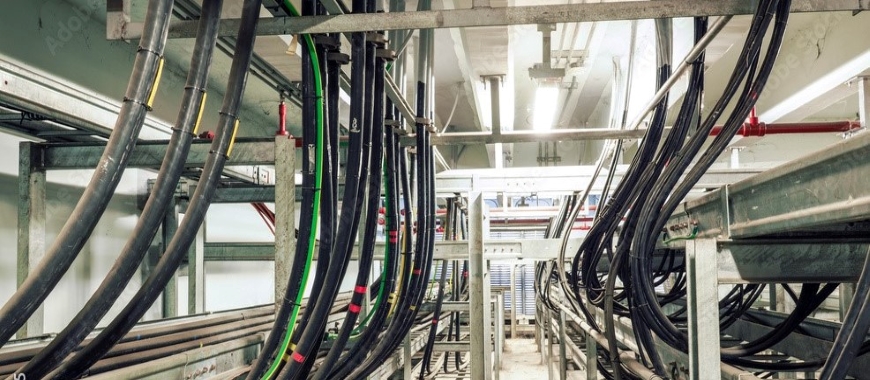
Cross bonding cable tray systems play a crucial role in managing high-voltage power cables. In cable systems, cross bonding is a method used to reduce electrical losses caused by circulating currents within the cable sheath. This technique divides the cable into sections, with each section’s sheath connected in a way that balances and neutralizes induced voltage. Cross bonding cable tray setups are crucial in high-voltage power transmission, as they minimize energy loss and prevent overheating. Integrating Aluminium Cable Tray enhances efficiency by providing a lightweight, corrosion-resistant solution for effective cable management. By optimizing the current flow within the system, cross bonding ensures that high-voltage cables perform efficiently over long distances while maintaining overall system safety and reliability. A cross bonding cable tray reduces cable sheath losses by bonding tray sections with clamps or links, ensuring NEC-compliant grounding.
What Is Cross Bonding Cable Tray
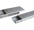
Cable trays are essential in modern electrical systems for organizing and supporting cables. These trays provide a structured way to manage cables, ensuring safety and order in installations. Selecting the best cable management tray is crucial for optimizing performance, as it ensures durability, proper airflow, and compatibility with the specific requirements of the system. Typically made of metal or other materials, they are used to hold power and communication cables, reducing clutter and preventing physical damage. Cable tray also allow for easy maintenance and cable inspections, ensuring that the overall system remains in good condition. Their open structure permits airflow, which helps prevent overheating in high-voltage environments. For effective cable management, especially in complex systems, using a well-structured tray system is critical.
Cross Bonding Cable Tray Integration
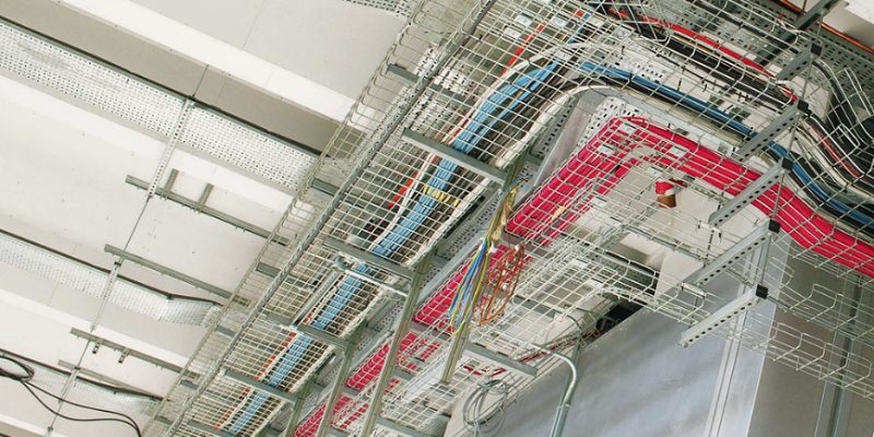
When implementing cross bonding into cable tray systems, careful design and planning are needed. Cross bonding cable tray systems help manage the induced voltages that occur when power cables carry high currents. The cables are sectioned, and each section’s metallic sheath is bonded in a specific configuration to reduce circulating currents. These circulating currents, if not controlled, can lead to additional heating, which reduces cable efficiency and increases the risk of system failures. Similarly, proper low voltage cable tray grounding is crucial to ensure electrical safety and system stability. It helps to prevent potential differences between tray sections, mitigates fault currents, and complements cross bonding efforts by neutralizing induced voltages, ensuring that the cable operates more efficiently and reliably.
Advantages of Cross Bonding in Cable Tray Systems
Integrating cross bonding in cable tray systems offers several advantages. First, it helps to minimize the heating effect caused by circulating currents. This reduction in heat ensures that cables can carry higher loads without compromising performance. Second, cross bonding extends the lifespan of the cables by maintaining a more stable operational environment. Lastly, by distributing the electrical load more evenly across the cable’s sheath, the cross bonding cable tray system improves overall safety and reliability.
The role of cable trays and how cross bonding integrates into these systems is essential for optimizing high-voltage power transmission. Cross bonding cable tray systems effectively reduce losses and prevent potential overheating, ensuring a safer and more efficient electrical infrastructure.
Capsule Cable Tray: Effective Solution for Cable Management
Best Practices for Cross Bonding Cable Tray Installation
Proper installation of cross bonding cable tray systems is critical for the effective operation of high-voltage power networks. Following best practices ensures that the system functions safely and efficiently. Several factors must be carefully managed during the installation process to reduce energy losses, prevent overheating, and ensure the longevity of the cables.
Key Considerations During Installation
- Cable Alignment and Support:
Proper alignment and support of cables within the cross bonding cable tray are essential. Cables must be securely fastened to prevent movement or sagging, which could result in physical stress or damage over time. Properly aligned cables also ensure better airflow, reducing the risk of overheating. - Accurate Sectionalizing of Cables:
Cross bonding requires sectionalizing cables into equal parts to effectively balance and neutralize induced voltage. The number and size of sections must be planned based on the cable’s length and current load. Poor sectionalizing can lead to an unbalanced system, causing inefficiencies and additional heating. - Correct Sheath Bonding Arrangements:
Sheath bonding must be done in a precise configuration to minimize circulating currents. The connections between the sheath and the bonding leads should be carefully monitored to ensure they are strong and reliable, preventing any future disruptions in the system. - Positioning of Junction Points:
The positioning of junction points where the cross bonding occurs plays a critical role in the system’s efficiency. These points should be located at specific intervals along the cable route to ensure optimal current flow and minimize voltage differences along the cable sheath. - Surge Protection:
Surge protection is vital, especially in long cable routes, where cross bonding could cause induced sheath voltages. Installing surge voltage limiters (SVLs) at strategic points helps to manage excessive voltages and protects the system from electrical surges.
Importance of Precise Connections and Positioning for Efficiency
The efficiency of a cross bonding cable tray system depends largely on the precision of connections and the correct positioning of key components. Precise connections ensure that the bonded sections function as intended, effectively neutralizing induced voltage. Even a small error in connection points or sectioning could lead to circulating currents, which increase heat and reduce cable performance. Positioning cross bonding sections at the right intervals prevents imbalances, ensuring that the cable system operates at maximum efficiency while minimizing energy loss and wear on the cables.
Adhering to these best practices for cross bonding cable tray installation is essential for maintaining a safe, efficient, and durable high-voltage cable system.
Cross Bonding Earthing Explained
Earthing is a crucial component in cross bonding cable tray systems, playing a vital role in ensuring electrical safety and reducing energy losses. Proper earthing ensures that electrical faults are directed safely into the ground, protecting both the system and the people working near it. In cross bonding systems, the earthing configuration is specifically designed to work in harmony with the cable sheath bonding, preventing hazardous circulating currents and improving overall efficiency.
The Role of Earthing in Cross Bonding Systems
In cross bonding cable tray systems, earthing serves as a protective measure that ensures excess electrical energy flows safely into the ground. This is particularly important in high-voltage systems where faults or surges can generate significant energy that must be controlled. Earthing helps to create a low-resistance path for fault currents, directing them away from sensitive equipment and minimizing the risk of damage. By connecting the metallic sheath of the cables to the earth, the earthing system ensures that no dangerous voltages are present on the sheath, preventing electrical hazards.
Additionally, earthing helps to control the induced voltages that occur when the cable is carrying a high current. Without proper earthing, these voltages could lead to an increased risk of electric shock or system malfunctions. In cross bonding systems, the earthing points are carefully placed to optimize current flow and reduce losses.
How Proper Earthing Enhances Electrical Safety
Proper earthing in a cross bonding cable tray system is essential for maintaining a safe and reliable electrical network. By creating a clear path for fault currents, earthing ensures that any excess electrical energy is safely dissipated into the ground. This prevents dangerous build-ups of voltage in the system, which could otherwise cause electrical shock or damage to equipment.
Moreover, proper earthing minimizes the occurrence of circulating currents in the cable sheath, which can lead to additional heating and energy loss. This not only enhances the efficiency of the system but also improves the longevity of the cables by reducing the stress placed on them. A well-designed earthing system also helps protect against electrical surges, further contributing to the overall safety of the cross bonding cable tray installation.
Earthing is a fundamental element of cross bonding cable tray systems, ensuring the safe operation of high-voltage power networks by providing an effective means to control fault currents and induced voltages. Proper earthing enhances both safety and efficiency, reducing the risk of system failures and ensuring reliable power transmission.
What is Sheath Bonding Cable and Why It Matters
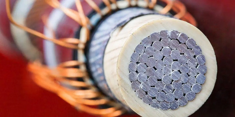
Sheath bonding is a critical aspect of high-voltage cable systems, especially when combined with cross bonding cable tray installations. It refers to the process of electrically connecting the metallic sheath of a cable to reduce losses and ensure safe operation. The metallic sheath serves multiple functions, including acting as a return path for fault currents, shielding against electromagnetic interference, and preventing moisture from entering the cable. Sheath bonding ensures that these functions are optimized, particularly in high-voltage power transmission systems, where proper bonding can significantly reduce energy losses and overheating.
Definition and Purpose of Sheath Bonding in Cable Systems
In cable systems, the metallic sheath provides protection and carries fault currents. Sheath bonding connects this sheath to a grounding system to manage the effects of induced currents. This is especially important in high-voltage systems, where significant currents can induce circulating currents in the sheath. These currents can increase the cable’s temperature and reduce its efficiency. The purpose of sheath bonding is to minimize these circulating currents and ensure the safe dissipation of fault currents, thus maintaining both safety and performance.
Differences Between Solid, Single-Point, and Cross Bonding Techniques
In cable tray systems, bonding techniques play a critical role in managing electrical losses, ensuring safety, and maintaining system efficiency. Solid bonding, single-point bonding, and cross bonding are three widely used methods, each suited for different voltage levels and installation requirements. The following table outlines the differences between these techniques, highlighting their advantages, limitations, and best-use scenarios.
| Feature | Solid Bonding | Single-Point Bonding | Cross Bonding |
|---|---|---|---|
| Connection Method | Sheath connected to ground at both ends (and sometimes midpoints). | Sheath bonded to ground at one end only. | Sectionalized sheath connections balance voltage. |
| Voltage Application | Low to medium voltage. | Long transmission lines, typically high voltage. | High-voltage systems requiring efficiency. |
| Circulating Currents | Present, causing potential overheating. | Eliminated, improving current rating. | Canceled out through sectionalization. |
| Induced Sheath Voltages | Minimal. | Higher, increasing with cable length. | Balanced, preventing voltage imbalances. |
| Efficiency | Simple but prone to losses. | Reduces losses but may cause voltage risks. | Most efficient, with minimal losses. |
| Safety | Can lead to excessive heating. | Reduces heating but may induce voltage risks. | High safety due to balanced voltages and no overheating. |
Classic Cable Tray: Reliable Support for Your Installations
Cross Bonding Cable Tray: Purpose and Applications
Cross bonding cable tray systems are pivotal in high-voltage power networks, designed to manage and minimize electrical losses while ensuring safety and operational efficiency. These systems utilize cross bonding link boxes, which are engineered to sectionalize and connect cable sheaths, neutralizing induced voltages and preventing circulating currents. Their applications span a variety of critical environments, particularly in large-scale power distribution systems where efficiency, reliability, and safety are of utmost importance. Below, we explore the purpose, functions, and key applications of cross bonding cable tray systems.
Purpose of Cross Bonding Cable Tray Systems
The primary goal of cross bonding cable tray systems is to reduce electrical energy losses caused by circulating currents within cable sheaths, which can lead to overheating and inefficiencies. By employing sectionalized sheath connections through cross bonding link boxes, these systems balance the induced voltage along the cable length, ensuring the power network operates efficiently and safely.
Functions of Cross Bonding Link Boxes
- Voltage Neutralization:
Link boxes eliminate induced voltages generated when cables carry high currents, maintaining a balanced voltage along the sheath. - Circulating Current Reduction:
By sectionalizing the cable sheath, link boxes minimize circulating currents that would otherwise cause heat and energy losses. - Safe Fault Current Transfer:
Link boxes provide secure pathways for fault currents, enhancing the safety of the power distribution network. - Ease of Maintenance:
They offer accessible points for connecting or disconnecting cable sections, simplifying troubleshooting and inspections. - Heat Management:
By reducing circulating currents, they help lower heat generation, contributing to the longevity of the cable system.
Applications in Power Distribution
Cross bonding cable tray systems are widely implemented in:
- Underground Transmission Networks:
Essential for managing the high currents and long cable runs in urban and industrial settings. - Substations:
Provide efficient energy transmission and help maintain system reliability. - High-Voltage Power Distribution:
Critical in reducing energy losses and ensuring safety in large-scale setups with extensive cable routes.
Cross bonding cable tray systems are indispensable in modern power distribution networks. By utilizing link boxes, they ensure optimal efficiency, reduced energy losses, and enhanced safety, making them essential for high-voltage installations in both urban and industrial environments.
Cross Bonding Cable Tray Meaning in Electrical Systems
Cross bonding is a crucial concept in high-voltage electrical systems, especially when integrated into a cross bonding cable tray setup. This method involves connecting different sections of a cable sheath to minimize the circulating currents induced by magnetic fields. These circulating currents can lead to additional heat and energy losses, reducing the system’s efficiency. Cross bonding neutralizes the voltages along the cable sheath by distributing them more evenly, ensuring that the system operates with minimal losses. This process is especially important in long cable runs where the risk of energy losses is higher due to greater distances.
Clarifying the Term and Its Significance in Reducing Losses
In a cross bonding cable tray system, cross bonding refers to the technique of dividing the cable sheath into smaller sections and connecting them in a way that balances the induced voltage. When a cable carries a high current, the magnetic field generated by this current induces circulating currents in the metallic sheath. If left unchecked, these circulating currents can lead to increased heating and, consequently, higher energy losses. Cross bonding effectively reduces these currents by allowing the induced voltages in different sections of the cable to cancel each other out through vector summation. This minimizes the heat generated in the cable sheath, improving overall system efficiency and performance.
The significance of cross bonding in electrical systems cannot be overstated. It not only helps in reducing energy losses but also extends the lifespan of the cables by preventing excessive heating. This is particularly important in high-voltage transmission systems, where long cable runs can otherwise lead to significant inefficiencies without proper bonding techniques.
Practical Examples of Cross Bonding in Cable Tray Installations
Cross bonding cable tray systems are commonly used in high-voltage power transmission networks, such as underground or long-distance transmission lines. In these installations, the cable is divided into sections, and each section’s sheath is cross bonded to the others. This reduces the circulating currents that would otherwise build up in the metallic sheath due to the large magnetic fields generated by the current-carrying conductors.
For example, in underground power transmission systems, the use of cross bonding cable tray setups helps manage the high levels of current that need to be safely transmitted over long distances. By reducing the heat generated by circulating currents, cross bonding ensures that the cables can carry higher loads without overheating. This allows for greater power transmission efficiency and reduces the need for costly cooling measures.
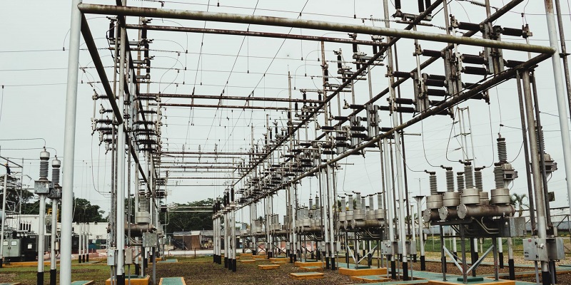
Additionally, cross bonding is often used in substations, where high-voltage cables are connected to transformers or switchgear. In these cases, cross bonding minimizes the losses caused by induced currents, ensuring that the system operates safely and efficiently.
Cross bonding in cable tray systems is an essential practice for reducing energy losses and improving the safety and efficiency of high-voltage electrical systems.
Cross Bonding Cable Tray Jumper Size and Design
In a cross bonding cable tray system, selecting the correct bonding jumper size and design is crucial for maintaining electrical safety and system efficiency. The bonding jumper connects different sections of the cable tray, ensuring electrical continuity and preventing potential hazards caused by stray currents. Choosing the right jumper size and designing the system for optimal performance requires careful consideration of various factors, including current load, cable size, and system layout.
Factors Affecting Jumper Size Selection
- Current Load Requirements:
The size of the bonding jumper must be chosen based on the amount of current that it needs to carry. In a cross bonding cable tray system, the jumper must be capable of safely carrying any fault current that may arise. Higher currents require larger bonding jumpers to avoid overheating or potential failure. - Cable Tray Material:
The size of the bonding jumper must be chosen based on the amount of current that it needs to carry. In a cross bonding cable tray system, the jumper must be capable of safely carrying any fault current that may arise. Higher currents require larger bonding jumpers to avoid overheating or potential failure. Additionally, the cable tray bonding jumper price should be factored into the selection process, ensuring a cost-effective choice that still meets safety and performance requirements. - Environmental Conditions:
Environmental factors, such as temperature and humidity, can influence the bonding jumper size. For instance, systems in high-temperature environments may require larger jumpers to prevent heat buildup, which could affect performance. Corrosive environments also call for corrosion-resistant bonding materials. - Cable Tray Layout:
The configuration and layout of the cable tray system impact the jumper size selection. In complex installations with long cable runs, multiple branching points, and the use of cable tray sheaves for cable installation, larger jumpers may be necessary. Cable tray sheaves help guide cables smoothly during installation, reducing mechanical stress, but their positioning and interaction with the tray layout must be carefully considered to maintain consistent electrical continuity across the entire system. - Standards and Regulations:
Adhering to relevant electrical standards and codes is essential when selecting the jumper size. These standards provide guidelines for minimum sizes based on current ratings and installation types, ensuring that the bonding jumper meets safety and performance requirements.
Design Considerations for Optimal Electrical Performance
- Ensuring Electrical Continuity:
The primary purpose of the bonding jumper in a cross bonding cable tray system is to ensure electrical continuity between all sections of the cable tray. Careful design is required to position the jumpers at strategic points along the tray to maintain this continuity without gaps or weak points. - Minimizing Voltage Drops:
Voltage drop is a key factor in the design of bonding jumpers. A well-designed cross bonding cable tray system minimizes the potential for voltage drops across the bonding jumper connections, ensuring the system operates efficiently. This can be achieved by selecting the appropriate jumper size and ensuring that all connections are secure and free of corrosion. - Fault Current Protection:
The bonding jumper must be capable of carrying fault currents without damage. This requires the design to consider the maximum expected fault current in the system and to select jumper sizes and materials that can handle these loads safely. - Mechanical Durability:
In addition to electrical considerations, the bonding jumper design must also account for mechanical factors. The jumper should be flexible enough to allow for any movements or shifts in the cable tray, but also strong enough to withstand physical stresses over time. - System Expansion Flexibility:
Future expansion of the cross bonding cable tray system should be considered during the design process. The bonding jumper design should allow for easy upgrades or extensions of the system without the need for significant redesign or replacement of the jumpers.
Selecting the right bonding jumper size and designing the system carefully are essential for the safe and efficient operation of a cross bonding cable tray system. By considering current load, material, environmental conditions, and electrical standards, you can ensure that the system operates reliably and meets all performance requirements.
Minimizing Losses in Cross Bonding Cable Tray Systems
In high-voltage electrical networks, minimizing energy losses is essential for maintaining efficiency and safety. Cross bonding cable tray systems are designed to reduce circulating and eddy current losses, which can otherwise lead to excessive heat generation and decreased performance. By applying effective methods and techniques, these losses can be significantly reduced, ensuring the system operates at optimal efficiency.
Methods to Reduce Circulating and Eddy Current Losses
- Sectionalizing the Cable Sheath
In a cross bonding cable tray system, sectionalizing the cable sheath into smaller, equal sections helps minimize circulating currents. When the cable sheath is divided, the induced voltages in each section can be balanced and neutralized through vector summation. This effectively reduces the circulating currents that flow along the sheath, preventing unnecessary energy losses. - Precise Placement of Bonding Points
Correctly placing the bonding points at regular intervals is key to reducing circulating current losses. Each bonding point must be positioned to ensure that induced voltages are neutralized across all sections of the cable. The precise alignment of these bonding points ensures that circulating currents are minimized, and the system can operate more efficiently. - Use of Quality Conductors
High-quality conductors should be used to reduce the resistance within the bonding system. Lower resistance helps prevent the buildup of circulating currents, as less energy is lost through heat. Choosing conductors with low resistivity is crucial for ensuring that the cross bonding cable tray system remains efficient and safe. - Mitigating Eddy Currents with Proper Design
Eddy currents, which flow radially and longitudinally within the sheath, are typically smaller than circulating currents but can still cause heat loss. Proper design and the use of non-magnetic materials in the construction of the cable tray can help reduce the magnitude of eddy currents. This further enhances the system’s efficiency by preventing heat buildup.
Enhancing System Efficiency Through Proper Bonding
- Balancing Electrical Loads
In a cross bonding cable tray system, proper bonding helps balance electrical loads across the entire cable. By ensuring that the electrical current is evenly distributed, the system can operate with fewer energy losses and at higher efficiency. Balanced electrical loads also reduce the risk of overheating and extend the lifespan of the cables. - Improving Heat Dissipation
Effective bonding in a cross bonding cable tray system allows for better heat dissipation. By reducing circulating currents and eddy currents, the amount of heat generated is minimized, preventing the cable system from overheating. Incorporating ventilated cable trays into the system further aids in heat dissipation by enhancing airflow around the cables. This combined approach improves system performance while contributing to the safety and longevity of the cables. - Preventing Voltage Imbalances
Proper bonding prevents voltage imbalances along the cable sheath, which can lead to excessive current flow and higher energy losses. By carefully designing and maintaining the cross bonding system, voltage imbalances are minimized, ensuring that the system operates efficiently without excessive heat generation or power loss. - Increasing Cable Current Ratings
When circulating current losses are reduced through cross bonding, the cable’s current-carrying capacity is increased. This allows the system to handle higher loads without risking overheating or energy loss. Proper bonding ensures that the system remains efficient, even when carrying higher current levels.
Economical Cable Tray for Affordable and Organized Wiring
Cross Bonding Cable Tray for High Voltage Applications
Cross bonding cable tray systems are widely used in high-voltage cable applications, particularly in power transmission and distribution networks. These systems are designed to manage the large electrical currents that flow through high-voltage cables, ensuring that the power is transmitted efficiently and safely over long distances. Cross bonding plays a critical role in reducing electrical losses, minimizing heat generation, and maintaining system integrity.
Applications in High-Voltage Cable Systems
In high-voltage cable systems, cross bonding cable trays are essential for managing the induced voltages that arise due to the large magnetic fields generated by current flow. These trays provide an organized structure for managing multiple cables, allowing for better airflow and reducing the risk of overheating. By sectionalizing the cable sheath and bonding it in a way that neutralizes induced voltages, cross bonding ensures that circulating currents are minimized. This is particularly important in underground or long-distance transmission systems where energy losses can accumulate if not properly managed.
Additionally, cross bonding cable tray systems are commonly used in power distribution facilities, substations, and industrial environments. They help ensure that power is transmitted reliably across long cable runs, maintaining system efficiency and safety. Proper cross bonding helps to prevent voltage imbalances that could lead to system failures or equipment damage.
Benefits for Power Transmission and Distribution
The primary benefit of using cross bonding cable tray systems in high-voltage applications is the reduction of circulating currents. These currents can cause significant energy losses and generate excessive heat if not properly managed. By neutralizing these currents, cross bonding allows the cable to carry higher loads without risking damage or inefficiencies.
Another key benefit is the improved lifespan of the cables. When circulating currents and heat generation are minimized, the physical stress on the cables is reduced. This leads to longer operational life and fewer maintenance requirements, ultimately saving costs and improving the reliability of the power transmission system.
Cross bonding cable tray systems also contribute to greater system safety. By preventing excessive heat buildup and reducing the risk of electrical faults, these systems help protect both the infrastructure and personnel working with the cables. The even distribution of electrical loads across the cable system ensures consistent performance, further enhancing the safety and reliability of power transmission networks.
The Importance of Cross Bonding in Cable Tray Systems
Cross bonding cable tray systems play a vital role in high-voltage applications, ensuring the efficient and safe transmission of power over long distances. They reduce circulating current losses, improve heat dissipation, and extend the lifespan of the cables. Additionally, they contribute to system safety by minimizing the risk of overheating and voltage imbalances.
In summary, cross bonding cable tray systems are indispensable in high-voltage power transmission and distribution. They help to optimize system performance, reduce maintenance needs, and ensure the reliability of the entire power network. For any large-scale electrical system, implementing a well-designed cross bonding cable tray system is essential for long-term operational success.
Cable Connection Methods and the Role of Cross Bonding Cable Tray
Different cable connection methods are essential in managing electrical performance, grounding, and safety in power and communication systems. Each method serves specific purposes and influences the design and type of cable trays required. Here’s an overview of key connection methods and the critical role of cross bonding cable trays.
Cable Connection Methods
- Single-Point Grounding
- Description: Grounding occurs at one end of the cable sheath.
- Application: Used to prevent circulating currents in long cable runs.
- Tray Requirements: Insulated trays to isolate the grounded section and prevent fault propagation.
- Midpoint Grounding
- Description: The cable sheath is grounded at its midpoint.
- Application: Common in medium-length cables to balance induced voltages.
- Tray Requirements: Supports proper routing to accommodate midpoint grounding installations.
- Double-Point Grounding
- Description: The sheath is grounded at both ends, creating a continuous grounding path.
- Application: Used in low- or medium-voltage systems where circulating currents are acceptable.
- Tray Requirements: Conductive trays bonded to ensure continuous grounding.
- Cross-Connection
- Description: Cable sections are interconnected to transfer fault currents and balance voltages.
- Application: Facilitates efficient current flow and ensures fault mitigation.
- Tray Requirements: Strong grounding support to secure interconnections.
- Cable Transposition Cross-Connection
- Description: Cables are transposed to reduce electromagnetic interference (EMI) and balance load distribution.
- Application: Used in high-voltage systems to minimize interference.
- Tray Requirements: Wide and structured trays to support transposition configurations.
Role of Cross Bonding Cable Tray in Cable Connection
The Cross Bonding Cable Tray is vital for ensuring proper functioning and safety across these connection methods, especially in high-voltage systems. Here’s why:
- Voltage Neutralization: In methods like single-point or cross-connection, the tray system ensures the induced voltages are effectively neutralized.
- Reduced Losses: By supporting cross bonding link boxes, the tray minimizes circulating currents, preventing overheating and improving efficiency.
- Ground Continuity: Provides a reliable path for grounding connections, critical in double-point and midpoint grounding setups.
- Enhanced Safety: Protects cables from external influences and ensures electrical energy is safely managed.
- System Longevity: Proper grounding and neutralization facilitated by the tray extend the lifespan of cables and associated equipment.
The cross bonding cable tray is a cornerstone in ensuring the effectiveness and safety of various cable connection methods, offering optimal performance in both power distribution and communication networks.
FAQs about Cross Bonding Cable Tray
Cable cross bonding is a method used in electrical systems to minimize energy losses caused by circulating currents in cable sheaths. In this process, the cable sheath is divided into multiple sections. Each section is bonded in a way that balances the induced voltage through vector summation, effectively reducing the circulating currents. This helps prevent excessive heating and energy loss. Cross bonding is particularly important in high-voltage systems, where long cable runs can generate significant electrical losses if not properly managed. By implementing cross bonding, the efficiency and lifespan of the cable system are improved, and it ensures that power is transmitted reliably and safely across large distances
The three main types of cable trays commonly used in electrical systems are ladder-type, solid-bottom, and wire mesh trays. Ladder-type trays are the most popular due to their strength and ability to support heavy cables. They also allow for easy airflow, which helps prevent overheating. Solid-bottom trays provide better protection for cables by fully enclosing them but may limit airflow. These trays are typically used in environments where the cables need extra shielding from dust or moisture. Wire mesh trays are lighter and offer flexibility in terms of installation. They are often used for supporting communication and fiber optic cables due to their lightweight nature. Each type of tray is chosen based on the specific requirements of the installation and the environment.
Yes, a cable tray needs to be bonded. Bonding ensures that all metallic components of the cable tray system are electrically connected, providing a continuous low-resistance path to ground. This is important for safety reasons, as it prevents the buildup of potential electrical hazards in the event of a fault. Proper bonding also helps prevent voltage differences that could lead to shock hazards or system damage. In a cross bonding cable tray system, bonding is particularly crucial to minimize circulating currents and reduce energy losses. Without proper bonding, the system may not operate efficiently, and the risk of electrical faults increases.
Equipotential bonding of cable trays is the process of connecting all metallic parts of the tray system to the same electrical potential, typically ground. This ensures that there are no voltage differences between various sections of the tray system, which could otherwise lead to dangerous electrical shocks or equipment damage. In cross bonding cable tray systems, equipotential bonding is essential for reducing circulating currents and preventing energy losses. By maintaining a consistent potential across all parts of the tray system, equipotential bonding enhances the safety and reliability of the entire electrical installation. It also helps ensure that fault currents are safely directed to the ground, protecting both equipment and personnel.
The National Electrical Code (NEC) provides guidelines for grounding cable trays under Article 392, specifically 392.60. This section mandates that cable trays made of metal must be effectively bonded and grounded to ensure electrical safety. Grounding is crucial for dissipating fault currents and preventing equipment damage. The NEC allows cable trays to serve as equipment grounding conductors (EGCs) if they meet certain conditions, such as being securely connected and having adequate cross-sectional area to handle fault currents. Additionally, Article 250 further specifies grounding and bonding requirements for electrical systems, including cable trays. These standards help ensure proper functionality and safety of the entire electrical installation. Regular inspection and maintenance are required to maintain the integrity of grounding connections in cable trays. For systems with cross-bonding techniques, grounding ensures the safe handling of fault currents distributed across multiple cable trays or pathways.
A cross cable, commonly called a crossover cable, is a type of Ethernet cable used to connect two devices of the same type directly, such as two computers or two network switches, without a hub or switch. It swaps the sending and receiving wires, ensuring proper data transmission. For example, in a T568A to T568B configuration, the transmit pins of one device connect to the receive pins of the other. In networking setups involving cable trays, cross cables might be used to optimize the routing of connections between devices in distributed systems. These cables are less common today due to the widespread use of auto-sensing Ethernet ports, which automatically adjust connections. However, cross cables remain useful for legacy systems or specific scenarios where devices lack auto-sensing capabilities.
A crosslink (crossover) cable is typically used to directly connect two similar devices, such as connecting two computers or switches without an intermediary device like a hub. In the context of cable trays, crosslink cables can be beneficial in data centers or industrial setups where devices on the same network need localized connectivity for faster data exchange. This might involve cross-bonding within cable tray systems to ensure minimal interference and efficient routing. For example, crosslink cables may be employed when setting up failover systems or temporary networks where traditional Ethernet infrastructure isn’t practical. In scenarios involving power and signal separation within trays, crosslink cables can be laid out to minimize crosstalk and signal degradation.
Bonded cables have tightly bound pairs of wires, enhancing uniformity and reducing crosstalk. They are typically used in environments where consistent performance over long distances or challenging installations is critical, such as in industrial cable tray systems. The physical bonding also increases durability during handling.
Unbonded cables, in contrast, have separate wire pairs, making them more flexible and easier to install in confined spaces. They are suitable for shorter distances or less demanding environments.
In cable tray systems with cross-bonding, bonded cables may offer better performance in reducing electromagnetic interference (EMI), especially in high-noise environments. Unbonded cables, while less robust, provide cost savings and easier installation when flexibility is required. Both types are selected based on application needs, performance requirements, and installation conditions.
Crossover cables and patch cables serve distinct purposes in Ethernet networking.
Crossover cables connect two similar devices, like computers or switches, by crossing the transmit and receive wires. They are essential in setups without auto-sensing ports, ensuring proper communication.
Patch cables, on the other hand, are straight-through cables used to connect different devices, such as a computer to a switch or router.
In cross-bonded cable tray systems, the choice between the two depends on the network design. For direct device-to-device connections within the tray, crossover cables are used. For connections extending to switches or patch panels, patch cables are preferred. Patch cables are more commonly used today due to advancements in Ethernet ports that automatically handle cross-connections. Proper identification and labeling are essential when managing these cables in large-scale tray systems to avoid misconfigurations.

As the editor of GangLong Fiberglass, I have years of experience and in-depth research, focusing on cable tray products, fiberglass solutions, and grille systems. I incorporate years of industry insights and practical experience into every content, committed to promoting the progress of the industry. At GangLong Fiberglass, my commitment is reflected in every product, from innovative cable trays to durable fiberglass solutions and sturdy grille systems. As an authoritative voice in the industry, my goal is to provide valuable information to professionals and businesses and promote forward-looking solutions.

